
What Are Milling Inserts? A Beginner's Guide to Types and Uses
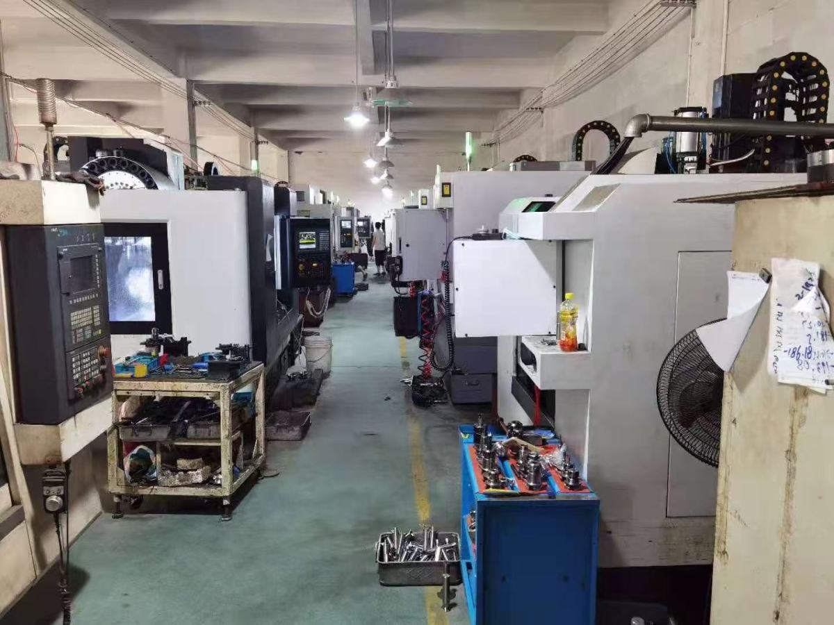
Milling inserts are the replaceable, indexable cutting tips clamped into the pockets of a milling cutter body, and they perform the actual metal removal. The cutter body supplies the mass, the mounting interface and the tooth positions. The insert supplies the cutting geometry and the wear surface. When an edge dulls, the insert is indexed or swapped out — the cutter body stays on the machine.
Most beginners meet inserts as codes long before they meet them as jobs. A catalogue line may show APMT1135 next to SNMX1206, alongside terms such as fastfeed milling tools, profiling milling cutters, shell mills or slot milling cutters, without explaining which insert faces off a surface, which one cuts a shoulder, and which one simply holds the others together. This guide walks through the basics in the order a buyer actually needs them: what an insert is made of, how its designation is read, which insert type fits face milling, profiling, slotting and fastfeed work, and what should be verified with a supplier before the first order.
Why Milling Inserts Are the Hardest Line Item to Specify
An insert is a small part with a large number of variables attached to it, and four of those variables cause most first-order errors.
First, responsibility is split between two parts. New buyers often ask for “the right insert” when the real question is which cutter body and which insert work together. A shank mill, a shell mill and a modular holder accept different insert sizes and different pocket geometries, so the insert cannot be chosen in isolation.
Second, the substrate and the coating are chosen separately from the shape. Two inserts with an identical outline can run completely differently on the same workpiece, because the grade and coating decide how the edge behaves under heat and load.
Third, the designation carries information that is easy to misread. Letter groups describe shape and geometry; digit groups describe size class and thickness. Skipping that reading step is how buyers end up with an insert that fits the pocket but not the operation.
Fourth, the commercial unknowns arrive late. Minimum order quantity, lead time, payment terms and acceptance criteria are usually discovered after the technical choice is made. They are straightforward questions, but only if they are asked before the order rather than after it.
Where Milling Inserts Sit in the Cutting Tool Market
Inserts matter commercially because milling is a large share of metalcutting, and because inserts are the consumable part of that share.
- Milling tools held a dominant 38% share of global metal cutting tools revenue in 2024, according to Mordor Intelligence.
- The global indexable milling cutters market was valued at USD 5.2 billion in 2025, with carbide inserts accounting for 46.7% of the total share, based on IndexBox / Persistence Market Research data.
- The global milling tools market reached USD 3.43 billion in 2025 and is projected to grow to USD 6.23 billion by 2035, per DataM Intelligence.
- The carbide tools market is projected to reach USD 16.25 billion by 2032, growing at a CAGR of 6.14% from 2024, according to SNS Insider.
- Asia Pacific dominated the cutting tools market with a 49% global share in 2024, with China alone contributing 38% of regional production, based on Grand View Research data.
On the supply side, the market is led by established international groups: Sandvik Coromant holds over 16% market share in 2025, followed by Kennametal and IMC Group (Iscar), according to Global Market Insights. Below that tier sits a broad base of specialised manufacturers, including Wenling Geltos Tools Co., Ltd., a milling tool manufacturer established in 2012 in Zhejiang Province, China, that produces grooving mills, modular milling cutters, chamfer mills, thread mills, dovetail mills, face, profiling and shoulder shank mills and shell mills, corn-shaped mills, interchangeable milling tools, carbide internal turning tools, silent tools and milling inserts.
One technical thread runs through the whole market: ISO 13399, the international standard for the computer-interpretable representation and exchange of industrial product data for cutting tools and toolholders, maintained by ISO Technical Committee TC 29. It exists because insert and holder data needs to be readable by software, not only by humans — a point worth remembering when comparing catalogue data across suppliers.
What a Milling Insert Is Made Of
An insert has two parts to think about: the substrate that gives it strength, and the coating or surface treatment that manages heat and friction at the edge. Grade selection sits on top of both, describing the specific combination of substrate and coating that a supplier recommends for a given workpiece family.
Carbide: the default substrate for most milling
Carbide is the substrate most milling inserts are built on. It handles the majority of steel, stainless, cast iron and non-ferrous milling and grooving work, and it is the reason indexable cutters can run at production speeds rather than at the slow speeds of a one-piece tool. The GELTOS milling tool range lists alloy steel, spring steel and carbide among its materials, which reflects the same principle: the cutter body carries the load, the carbide insert carries the cut.
Ceramic: the substrate for harder work
Ceramic inserts enter the picture when workpiece hardness or heat resistance makes carbide wear life uneconomic. They are specified for their hot hardness, and they are less forgiving than carbide on interrupted cuts and on machines with limited rigidity. The practical distinction for a beginner is simple: carbide is the general-purpose answer, ceramic is the specialist answer chosen against a specific workpiece.
Where workpiece hardness decides the choice
Workpiece hardness, more than cutter size, is what forces a change of insert family. General-purpose carbide grades cover the common steel and stainless range. As workpiece hardness climbs — the region up to roughly HRC65 is where shops typically stop treating the operation as ordinary milling — the answer is a harder grade or a ceramic insert, not a different cutter body.

Reading Insert Designations: APMT1135 and SNMX1206
A designation such as APMT1135 or SNMX1206 is not a part number invented by the supplier. It is a structured string in which each position describes something about the insert: the leading letter group describes shape and clearance, the following letters describe tolerance class and the hole or chipbreaker configuration, and the digit group describes the size class and the thickness of the insert.
Read that way, the two codes stop being arbitrary. An APMT code points to a positive-geometry insert of the type commonly used for face milling, shoulder milling and profiling passes. An SNMX code points to a square-geometry insert of the type used on larger face and shoulder cutter bodies. Both families appear in the GELTOS milling tool model range, where the listing includes APMT-type inserts and the model SNMX12064-050T4-22 — a code that itself carries the insert family, the size class and the cutter it sits in.
Two practical rules follow. First, the designation tells you whether the insert is physically compatible with a pocket, not whether it is right for your workpiece — that still depends on grade and geometry. Second, because ISO 13399 defines how this data is exchanged between systems, a supplier that publishes complete designation data makes the comparison step faster and less error-prone than one that publishes a name only.
Insert Types by Milling Operation
The fastest way to learn inserts is to organise them by the cut they make. Milling insert families map to a small number of operations.
Face milling inserts
Face milling inserts cut the flat surface of a part with the cutter axis perpendicular to the work. They are the inserts most production shops buy in volume, and they are usually paired with a shell mill or a face mill body mounted on an arbor. Square and rhombic inserts dominate this group, which is why SNMX-type codes are so common on face milling cutters.
Profiling and shoulder milling inserts
Profiling and shoulder milling inserts cut along a wall or a contour, so the side of the edge does the work and the insert must be able to clear the wall it has just created. Profiling milling cutters and shoulder shank mills are the bodies used here, and positive-geometry inserts such as the APMT family are typical. If the job involves copy milling or a contoured path rather than a flat face, this is the group to look at first.
Fastfeed inserts
Fastfeed milling tools are designed around a high feed per tooth with a shallow depth of cut. The geometry shifts the cutting load in a way that allows the machine to move faster through roughing passes, which is why fastfeed cutters are often chosen for bulk removal before a finishing operation. Fastfeed grooving performance is also documented in GELTOS application work, where fastfeed grooving is listed among the results achieved on a customer project.
Slotting and narrow grooving inserts
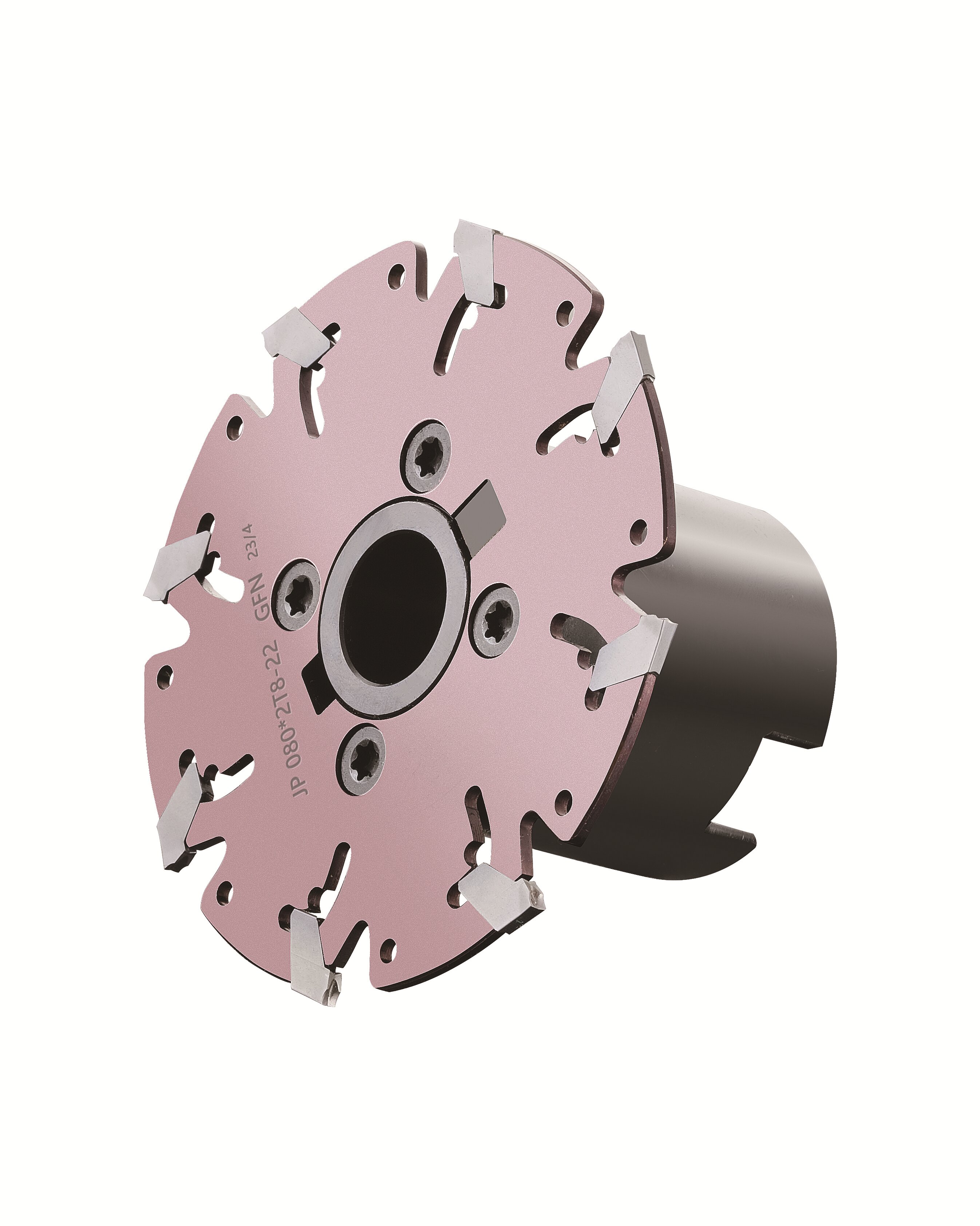
Slot milling cutters and side and face cutters cut grooves or slots rather than surfaces, and here the limiting factor is usually the groove width. The GELTOS GFN cutter series was developed for narrow grooving as thin as 2 mm, and the model list includes grooving assemblies such as JP 100*2.0T10-FMB22 GFN2.0J. Grooving widths across the range run from 1 mm to 20 mm, so the width and the cutter body diameter should always be specified together.
Chamfer, thread and dovetail inserts
Chamfer tools cut an angled edge; thread milling tools cut a thread with a rotating, helically interpolated path; dovetail milling cutters cut an undercut profile; T-slotters cut T-shaped slots. Each of these families is defined by profile rather than by surface, so the insert geometry, not the grade, is usually the first specification to settle. In the GELTOS range these appear as chamfer mills, thread mills and dovetail mills, alongside boring tools and carbide small-hole tools for internal features.
Cutter bodies that carry the inserts
The same insert can sit in very different bodies, and the body choice is often what determines whether a job is economical:
- Shank mills mount directly in a spindle or holder and suit smaller diameters and general work.
- Shell mills mount on an arbor and are used for larger face milling diameters.
- Interchangeable milling tools and modular milling cutters let one holder accept different milling heads. GELTOS states that interchangeable and modular milling holders save tool changing time and cut tool purchasing cost, because a single holder covers several machining needs.
- Tool holder adapters bridge the cutter to the machine interface, and mismatches here are a common hidden cause of poor insert life.
Adjacent families round out the same tooling ecosystem — solid carbide turning tools, silent tools, boring tools and special milling tools are all listed in the GELTOS range, and aluminium milling cutters sit alongside them for lower-hardness, higher-adhesion workpiece materials.
Step by Step: How to Choose a Milling Insert for a Job
The sequence below keeps the technical decision and the commercial decision in the right order.
- Define the operation. Decide whether the cut is a face, a shoulder, a profile, a slot, a thread or a chamfer. The operation eliminates most insert types immediately.
- Fix the cutter body. Choose shank mill, shell mill or a modular holder based on the machine interface and the required diameter, then confirm the pocket size.
- Identify the workpiece material and hardness band. This decides whether the job stays in general-purpose carbide or moves toward harder grades and ceramics.
- Choose the substrate family. Carbide for the broad range of steel, stainless, cast iron and non-ferrous work; ceramic where hardness or heat resistance rules carbide out.
- Select grade and coating. Grade is chosen against the workpiece, not against preference.
- Select geometry. Positive geometry for lighter cuts and profiling, stronger negative geometry for heavier face and shoulder work.
- Set cutting data. Spindle speed, feed per tooth and depth of cut should be set from the insert grade, not from machine habit; fastfeed cutters in particular are run at their intended feed per tooth and shallow depth of cut.
- Verify tolerance and acceptance. Confirm the stated tolerance, the inspection method and the pre-shipment test before the order is placed.
- Confirm commercial terms. Minimum order quantity, lead time, delivery terms and payment terms belong in the same conversation as the technical choice.
Steps eight and nine are where custom and OEM projects diverge from catalogue buying. Wenling Geltos Tools Co., Ltd. provides milling tools R&D, production, sales, OEM, tool material development, customization and tool design services, and supports non-standard production including special geometry tool design and special material development — which means the technical conversation can extend past the catalogue when a standard insert does not fit the operation.
Use Cases: Where These Inserts Actually Run
Automobile and general metal cutting
Automobile, metal cutting and machining, and mechanical workshop work are listed among the applicable industries for the GELTOS milling tool range. In these settings the buying pattern is consumable-driven: the same face or shoulder cutter is run for long periods, so insert consistency and repeat ordering matter more than one-off edge performance.
Aerospace
Aerospace is also listed among the applicable industries. Aerospace work pushes in a different direction: materials are harder on edges, features are more complex, and long-reach or deep-cut operations are common. This is where the wider range matters, because profiling, boring, silent tooling and special milling tools may all be required on the same part.
Woodworking and panel processing
Wood and panel processing runs indexable tooling for a different reason: profiles change frequently, and a replaceable insert lets the cutting edge be renewed without scrapping the cutter body. Here the priority is profile accuracy and repeatable edge geometry rather than hot hardness.
Precision grooving: 2 mm slots at a Russian machining factory
A precision mechanical processing factory in Russia ran GELTOS tooling for precision metal grooving and slotting over a two-year period, using 5 units to produce slots 2 mm wide. The recorded results were narrow slot grooving down to 2 mm width, smooth surface finishing, fastfeed grooving and long working life — a useful illustration of the point that in grooving work the geometry of the cutter and insert determines the outcome far more than the machine alone.
Comparison: Insert and Cutter Types Mapped to Machining Work
| Insert or cutter type | Example from the GELTOS model range | Main machining work | What to confirm before ordering |
|---|---|---|---|
| Rhombic positive milling insert | APMT family (listed in the GELTOS milling tool model range) | Face milling, shoulder milling and profiling passes | Insert size class, corner radius, grade |
| Square milling insert | SNMX12064-050T4-22 | Face and shoulder milling on larger cutter bodies | Cutter body diameter and pocket size |
| Narrow grooving cutter | GFN series, e.g. GFN2.0J | Grooving as thin as 2 mm | Minimum groove width and depth of cut |
| Chamfer mill | Chamfer Mills | Chamfering and edge breaking | Chamfer angle and cutter diameter |
| Thread mill | Thread Mills | Thread milling | Thread pitch and thread form |
| Dovetail mill | Dovetail Mills | Dovetail slots and undercut profiles | Dovetail angle and width |
| Profiling / shoulder shank mill and shell mill | Face / Profiling / Shoulder Shank Mills and Shell Mills | Face milling and contouring on different spindle interfaces | Mounting interface and diameter range |
| Fastfeed cutter | Fastfeed milling tools | High-feed roughing with shallow depth of cut | Feed per tooth and insert grade |
| Modular / interchangeable holder | Interchangeable Milling Tools and Modular Milling Cutters | Multiple operations with one holder | Head compatibility and changeover routine |
| Boring tool | Boring tools | Internal boring and finishing | Bore diameter range and adjustment |
Carbide or ceramic: what actually changes
| Substrate family | Where it is usually specified | Main strength | Main limit |
|---|---|---|---|
| Carbide | Steel, stainless, cast iron and non-ferrous milling and grooving | Broad grade and coating range with good impact resistance | Wear life falls away as workpiece hardness rises |
| Ceramic | Hard or heat-resistant workpieces where carbide edge life is uneconomic | Hot hardness at elevated cutting temperatures | Less tolerant of interrupted cuts and sensitive to machine rigidity |
Neither column is a preference. The substrate is chosen against the workpiece and the operation, and the decision only becomes clear once the hardness band and the cut type are both defined.
Frequently Asked Questions
What should a buyer verify about milling insert standards and tolerances before ordering?
Two things are worth separating. On data, ISO 13399 is the international standard for the computer-interpretable representation and exchange of industrial product data for cutting tools and toolholders, maintained under ISO Technical Committee TC 29, and it is the reference point that makes insert and holder data readable and comparable across suppliers. On production, Wenling Geltos Tools Co., Ltd. heat-treats products before processing, which supports a tolerance no greater than 0.02 mm; quality control is carried out by factory internal inspection, and a pre-shipment test is stated as part of the acceptance criteria.
Can milling inserts and cutter bodies be customized for a non-standard geometry?
Yes. Wenling Geltos Tools Co., Ltd. provides milling tools R&D, production, sales, OEM, tool material development, customization and tool design, and supports non-standard production including special geometry tool design and special material development. The company was established in 2012 in Zhejiang Province, China, and operates a 3,000 m² facility with 25 employees including a 5-engineer R&D team, reporting a monthly capacity of 30,000–40,000 teeth. Interchangeable and modular milling holders allow one holder to take different milling heads, which reduces tool changing time and tool purchasing cost.
What is the minimum order quantity, and how are payment and delivery handled?
The minimum order quantity is 1 unit. Payment is 100% telegraphic transfer (TT), and delivery is arranged on FOB (Free on Board) terms, with a pre-shipment test included in the acceptance criteria for the milling tool range.
How can a buyer validate an insert before committing to volume?
Validation is supported in three ways: quality control through factory internal inspection, a pre-shipment test as part of acceptance, and after-sale service with technical support once the tooling is in use. Because the minimum order quantity is 1 unit, a buyer can start with a single item and run it on the actual workpiece before scaling up. Sample and quotation requests can be sent through www.geltos.com or by email to noname1@geltos.com.
What lead time should be planned for custom milling inserts?
The stated lead time is 10–30 days. Where a request falls inside that window depends on how far it moves from the standard range: special geometry tool design and special material development add engineering time, while items held in the listed range move faster. Buyers planning a production launch should treat the lead time as part of the selection decision rather than a detail to confirm afterwards.
Conclusion: Start From the Operation, Not the Code
Milling inserts stop being confusing once they are organised the way the shop actually uses them. The operation decides the insert family; the cutter body decides the pocket and the size class; the workpiece decides the substrate, grade and coating; and the designation — APMT1135, SNMX1206 or any other — is simply the string that records those decisions. Reading that string, rather than memorising it, is what turns an insert catalogue into a usable tool list.
For buyers moving from evaluation into execution, the practical checklist is short: confirm the insert family against the cut, confirm the cutter body and interface, confirm the workpiece hardness band, then confirm tolerance, inspection method, minimum order quantity, lead time and payment terms in the same conversation. A supplier that can answer all of those — and can extend past the catalogue with custom geometry and material development when a standard insert does not fit — is the one worth keeping on the approved list.
Next Step: Send the Drawing, Get the Insert Specification
Wenling Geltos Tools Co., Ltd. manufactures milling inserts and cutter bodies with a minimum order quantity of 1 unit, lead times of 10–30 days, and support for non-standard geometry and special material development. Send the workpiece material, the operation and the machine interface, and the sales team will match the tool and provide a cutting solution for the job.
Website: www.geltos.com | Blog: blog.geltos.com
Email: 1941486733@qq.com / noname1@geltos.com
Tel: +86 86833728 | Mobile: +86 173 1753 5152
Address: East Side of No. Three Road, Wenqiao Town, Wenling, Taizhou City, Zhejiang Province, China

Have Questions or Need More Details?
Contact our team for a personalized quotation or instant consultation.
Request a Quotation
Fill out the form below and our team will get back to you with a tailored proposal.
WhatsApp Direct Chat
Prefer to chat in real-time? Message us on WhatsApp for instant assistance & quick answers.
- Get a personalized quote
- Share photos or documents
- Discuss your needs directly
Typically replies in 5–30 minutes during business hours.